Led Matrix
Intro
Make a 24X6 LED matrix
After making a 8X10 matrix a lot of people asked me about expanding the matrix to some thing bigger, and some wanted to write stuff to the matrix via a PC, so one day I looked at a pile of LEDs that I had leftover from a LED cube projected and I decided to make a bigger matrix with all the things people wanted.
So what are you waiting for? Get those LEDs out and heat up your soldering iron because we are about to make a 24X6 LED matrix!
Step 1
Getting All The Right Things
So you will need the basic set of tools for this project : a soldering iron, some solder wire, a cutter, a needle nosed plier,some wire, wire striper, and some desoldering tools if you need them.
For the matrix you will:
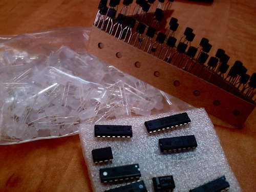
1. 144 LEDs
2. 24 resistors( The value is determent by the type of LEDs, in my case 91 ohm)
3. 4017 decade counter
4. 6 1KOhm resistors
5. 6 2N3904 transistors
6. A long Perfboard
7. Arduino
8. 3 x 74HC595 shift register
10. some pin headers
Getting All The Right Things
So you will need the basic set of tools for this project : a soldering iron, some solder wire, a cutter, a needle nosed plier,some wire, wire striper, and some desoldering tools if you need them.
For the matrix you will:
1. 144 LEDs
2. 24 resistors( The value is determent by the type of LEDs, in my case 91 ohm)
3. 4017 decade counter
4. 6 1KOhm resistors
5. 6 2N3904 transistors
6. A long Perfboard
7. Arduino
8. 3 x 74HC595 shift register
10. some pin headers

Step 2
How it works?
The tricky behind the display is multiplexing and the idea is the same as withe the 8x10 LED matrix: It is basically a way to split information in to little peaces and send it one by one.
this way you can save a lot of pins on the Arduino and keep your program quite simple.
Now this time we have 3 shift registers which multiply the number of outputs and save lots of arduino pins.
Each shift register has 8 outputs and you only need 3 arduino pins to control almost an limited numbers of shift registers.
We also use the 4017 decade counter to scan the rows, and you can scan up to 10 rows with it because you have only 10 outputs but to control it you need only 2 pins.
The 4017 is a very useful chip and it's a good idea to know how to work with it(http://www.doctronics.co.uk/4017.htm)
Like I said the scanning is done with the 4017, by connecting one row at a time to ground and sending the right data via the shift registers to the columns.
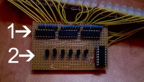
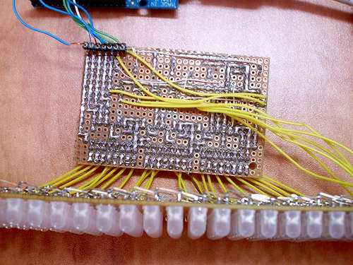
In Picture:
1- The 3 shift registers to control the rows
2- 4017 With 6 transistors for scaning the rows
1- The 3 shift registers to control the rows
2- 4017 With 6 transistors for scaning the rows
Step 3
Schematics
The only thing I didn't specified in the schematics is the value of the current limiting resistors because they change from each type of LEDs, so you will need to calculate them by your self.
Now to calculate the value of the 24 resistors you can use this site :
http://led.linear1.org/1led.wiz
You should first get some specs on your LEDs, you should know their forward voltage and forward current, you can get this info from the seller. The circuit operates on 5V so your Source voltage is 5V.
The pins that you see are the Adruno Pins.
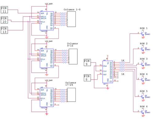
Click to see bigger.
Step 4
Soldering The LEDs
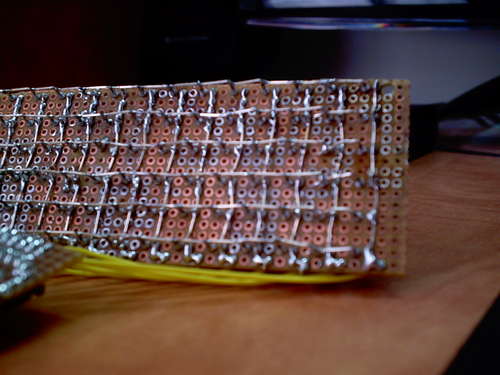
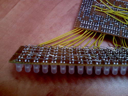
Soldering 144 LEDs in a matrix formation can be a little tricky if you don't have a general idea how.
The last time I soldered a matrix I used lots of little wire jumpers which was a pain to solder, so this time I was a little more creative and came up with this way.
You need to bend the positive lead of the LED down towards the other ones and make a column, and snip off the leads you didn't use and try to make the connections as low as you can get, and you do this to all of the positive leads.
Now the negative leads are connected in a column and thats make soldering tricky because the positive rows are in the way, so you will need to make a 90 degrees bend with the negative lead and make a bridge over the positive row to the next negative lead, and so on to the next LEDs.
Now I will not explain how to solder the shift registers and all the parts because every one has he's own style and methods.
Soldering The LEDs
Soldering 144 LEDs in a matrix formation can be a little tricky if you don't have a general idea how.
The last time I soldered a matrix I used lots of little wire jumpers which was a pain to solder, so this time I was a little more creative and came up with this way.
You need to bend the positive lead of the LED down towards the other ones and make a column, and snip off the leads you didn't use and try to make the connections as low as you can get, and you do this to all of the positive leads.
Now the negative leads are connected in a column and thats make soldering tricky because the positive rows are in the way, so you will need to make a 90 degrees bend with the negative lead and make a bridge over the positive row to the next negative lead, and so on to the next LEDs.
Now I will not explain how to solder the shift registers and all the parts because every one has he's own style and methods.
Step 5
Programming The Display
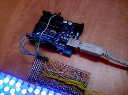
We are almost there, the only thing thats left is the program.
So far I wrote two programs for it that do pretty much the same thing.
I have added the program that gets a word or a sentence from the arduino IDE serial monitor and displays it on the matrix, my code is very basic and may be not the best in the world but it does the work, and you are free to write your own code and modify mine as you wish.
I have added an excel file so you can create your own symbols and characters.
The way it works is like so:
You create the symbol you want pixel by pixel(don't worry it's very easy) and copy the output line like so - #define {OUTPUT LINE}
I will add in the future a code for animations and a nice game of snake as soon as I have more time on my hands.
Programming The Display
We are almost there, the only thing thats left is the program.
So far I wrote two programs for it that do pretty much the same thing.
I have added the program that gets a word or a sentence from the arduino IDE serial monitor and displays it on the matrix, my code is very basic and may be not the best in the world but it does the work, and you are free to write your own code and modify mine as you wish.
I have added an excel file so you can create your own symbols and characters.
The way it works is like so:
You create the symbol you want pixel by pixel(don't worry it's very easy) and copy the output line like so - #define {OUTPUT LINE}
I will add in the future a code for animations and a nice game of snake as soon as I have more time on my hands.
| usb_scroll.txt |
| programming_the_display.htm |
Step 6
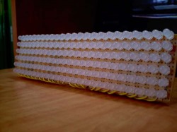
We Are Done!
Congratulations you made yourself a 24x6 matrix and now you can display anything you like on the fly.
Now try to play with it and come up with a new program and a better interface
We Are Done!
Congratulations you made yourself a 24x6 matrix and now you can display anything you like on the fly.
Now try to play with it and come up with a new program and a better interface
This project is owned by batterhead15. All credit is given to the owner and this project and its pictures are copy righted by batteryhead15.
This project along with it photos are used with permission.
This project along with it photos are used with permission.
©
